Domestic Ventilation Systems and Testing
In this document, a broad outline of domestic ventilation system type, installation, and testing will be given for guidance towards gaining building regulations compliance. This document will be primarily focused on decentralised System 1 and 3 extracts as the most common forms of the ventilation system.
Purpose of Ventilation
Ventilation is supplying and removing air from a building to improve the quality of air by removing pollutants and humidity.
Air may also be heated by the ventilation system to contribute to the comfort of a home.
Ventilation Systems and Compliance
There are four main systems for ventilation as defined in Building Regulations Approved Document Part F :
• Background ventilators and intermittent extract fans
• Passive stack ventilation
• Continuous mechanical extract
• Continuous mechanical supply and extract with heat recovery (MVHR)
The systems in detail:
System 1 – Extracts are installed into the utility, kitchen, toilets, and bathrooms which run when the room is in use (activated by lighting) or is activated by the occupant. The supply of air is through natural ventilation from trickle vents and uncontrolled airflow through the building.
System 2 – Vertical ducts are installed in utility, kitchen, toilets, and bathrooms which extend to the roof and rely on heat induced convection to force warm, polluted, or humid air up through the duct. The supply of air is through natural ventilation from trickle vents and uncontrolled airflow through the building.
System 3 – Extracts are installed into the utility, kitchen, toilets, and bathrooms which run continuously through out the day. They will run at a trickle rate when the room is unoccupied but operate at a boosted rate when the room is in use, either activated by the lights or occupant. The supply of air is through natural ventilation from trickle vents and uncontrolled airflow through the building.
This system can be centralised (“MEV” all supply and extract handled by a single unit) or decentralised (“dMEV” each wet room has a single fan installed).
System 4 – A centralised unit is installed which handles supply and extract but also has a heat exchange element, which recovers heat energy from the extracted air and heats the supplied air. This can be an on-demand function to maintain the temperature of the building all year round.
This system can be decentralised (each wet room has a single fan installed) but is generally undesirable as a single centralised unit is far more efficient.
System 2 has no compliance testing method and as such is exempt from any requirement for commissioning, otherwise all other systems must be tested and ventilation commissioned with results submitted to building control.
Fan Types
Axial Fans – Generally used in systems 1 and 3, the fan itself is much like a propeller, spinning with the axial plane in line with the airflow. Axial fans are lower power units that keep costs down, but the flow rates can suffer due to poor duct installation.
Centrifugal Fans – These can be used in systems 1 and 3, but typically are most effective in system 4 within centralised MVHR units or inline extracts. Centrifugal fans operate with the fan element spinning perpendicular to the airflow, usually resulting in a larger fan unit enclosure. These are generally much more powerful and do not succumb as easily to resistive duct installation.
Both fan designs will generate noise and vibration, so the correct choice of fan should be made with focusing on airflow requirement and serviceability.
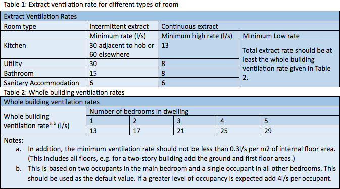
Target Performance Requirements
For system 1, 3, and 4 there are target air flow requirements which are outlined in the Building Regulations Approved Document Part F. These targets must be met for compliance.
Testing and commissioning of system 1 fans is by far the quickest and most simple method to gain compliance, followed by system 3 which requires calculations to be made before testing and commissioning is undertaken. System 4 MHVR units must be balanced, tested, and commissioned which makes it the most complex but complete ventilation solution.
Outline for Installation of Extracts and Ducting
It is essential that the “Domestic Ventilation Compliance Guide 2010” be used for guidance with duct type and proper installation methods, but below are some key points.
- Ensure the final location of equipment offers sufficient space to allow access for maintenance (and testing).
- The duct sleeve should be rigid. In situations where this is not possible, flexible ductwork may be used, providing extract ventilation rates are not compromised. Flexible ductwork should be pulled taught.
- Rigid ducts, rectangular or circular, should be used wherever possible. Where necessary, flexible ducts may be used, but their lengths should be kept to a minimum, connecting to rigid ductwork at the earliest opportunity.
- For flexible duct connected to axial fans, the length is limited to 1.5 metres; for centrifugal fans, the length limit is 6 metres (for extract rates 6 to 30 l/s), and 3 metres (for extract rates 31 to 60 l/s).
- The flexible duct should be pulled taught to ensure that the full internal diameter is obtained and flow resistance minimised. This is considered to have been achieved if the duct is extended to 90% of its maximum length.
- Horizontal ducting, including ducting in walls, should be arranged to slope slightly downwards away from the fan to prevent back flow of any moisture into the product.
- The minimum radius for a bend in a flexible duct must be equal to the diameter of the duct being used.
It is always beneficial to use no flexible duct where possible, but where it is not, any flexible duct must be taught and kept to an absolute minimum.
Any centralised system requires specialist installation methods and should be undertaken by a competent person.
Testing of extracts
Using a hooded vane anemometer is the most common and cost-effective method for measuring extract flow rate. This can be done from either the inside or outside by place the hood over the extract, ensuring that there is a seal around the hood, and taking an instantaneous reading.
Before testing the quality of the installation must be checked to ensure that the duct and extract are correctly fitted without air gaps and that airflow is uninterrupted within the duct to the outside.
To ensure the accuracy of the test result, it is best practice not to test with an external airspeed of 10m/s or greater as this will impact the result negatively.
Commissioning and Results
System 1 – System 1 fans are generally fixed speed and cannot be altered. As such, once the result has been taken there is no commissioning process, and any certificate issued will reflect the current capabilities of the individual extract.
Should the result be a failure, the extract or ducting should be assessed, and any performance shortcoming illuminated to improve the system. This may include adjusting or replacing either the extract or ducting depending on the issues raised.
System 2 – There is no testing or commissioning process for system 2 and as such will depend greatly on observations made long term within the building.
System 3 – Decentralised System 3 fans rely on operating at two speeds, for trickle and boosted flow rates. As such, they must meet individual flow requirement targets and a whole dwelling ventilation rate target.
Two results are taken, for the trickle and boosted rates, which if they meet the targets, will comply. But the trickle flow rates of all the extracts in the building must also sum to greater than the whole dwelling ventilation rate.
Should the result be a failure, the extract may be speed adjustable and can be made to comply and the whole dwelling ventilation rate may also be reached. Otherwise, if the fans are operating at maximum capacity and do not meet targets, the extract choice or system installation must be addressed.
In the case of a centralised unit, the system will need to be balanced for supply and extract, using the individual room targets calculated before testing. This also will require meeting the criteria for whole-dwelling ventilation rates.
System 4 – For this generally centralised system, calculations are required before testing to assess the targets on a room-by-room basis, for both extract and supply, and to meet whole dwelling ventilation rates. The process of balancing requires that adjustments be made to the outlets and inlets throughout the building ensuring that the fan unit is operating at optimal speed, whilst supplying and extracting at sufficient individual room rates and meeting the whole dwelling target rates.
The results are presented in much the same way as the system 3 extracts with a trickle and boosted flow rates for each room, for both supply and extract.
Failure to meet individual room flow rates or the whole dwelling ventilation rate will require further adjustment to the system or consideration given to the fan unit being incorrectly sized or ducting poorly installed. Contact
Ashby Energy Assessors.
Ashby Energy Assessors Blog and News